|
NC function
|
|
Controlled axis
|
Controlled, link axis: up to 5 feeding axes, 1 spindle, and 4 axes to link |
| Interpolation method: linear(G01) , circular (G02, G03), sine(G07) |
| Max. stroke: metric: 99999.999mm inch :9999.9999inch |
|
Setting increment |
Least input increment 0.001mm /metric 0.0001inch/inch |
| Least increment : X axis : 0.001mm / metric 0.0001inch/ inch
Y axis : 0.001mm / metric 0.0001inch/ inch
Z axis : 0.001mm / metric 0.0001inch/ inch |
| Max. traverse rate |
240 , 000mm /min or 9 , 600inch/min |
| Max. feedrate |
G94 : 150,000mm /min or 60 , 000.00inch /min |
| G95: 2 , 000.00mm /r or 200.0000inch/r |
| Automatic acceleration/deceleration: Execute the linear acceleration/deceleration to shorten the positioning time when automatically rapid feeding in Jog or Auto mode |
| Automatic acceleration/deceleration in cutting feed: automatic acceleration/ deceleration for cutting feed or manual continuous feed index, parameter setting the time constant from 8ms to 4000ms. |
| Buffer register: advance to read the instructions of the following two blocks to eliminate the interruption of NC instruction caused by reading the instructions to improve the working efficiency. |
|
MSTB function
|
Tool function T : • T2 digit/T4 digit • 99 groups tool offset • tool position offset ?tool length compensation |
| • tool radius compensation B/C • communication input of tool offset value
• tool length measure • tool life management |
| Spindle function S : • S2 digit/ S4 digit A(12 digit BCD output /analog output) • S4 digit B(12 digit BCD output/analog output )( 4-grade gear input ) • max. spindle speed limit. |
| auxiliary function M : specified by the sequential 2 digits after address M. End
of program : M02 • M30 , program stop : M00 , optional stop : M01 , subprogram call : M98 , end of subprogram : M99. Other M functions can exclusively be defined by user. |
| The second auxiliary function B: it is specified by the sequential 3 digitals behind B,
BCD signal of the three digitals are transmitted to the machine side. |
| The function is used for the positioning of graduation worktable. |
|
Precision compensation
|
?stored pitch error compensation: compensate the error caused by machine position to improve the processing precision and the compensated data is stored to the memory. |
| à¸à¹‘backlash compensation: compensating the loss momentum of machine |
| Tool length compensation and tool nose radius compensation : the tool length is specified by G codes ( G43 , G44 , G49 ) . |
| • tool nose radius compensation (G40 , G41 , G42), the compensation value for every tool is stored to the memory. |
| Max. compensation value: ± 999.999mm or ±99.9999inch. |
|
Reliability and safety
|
• emergency stop ; • overtravel ; • stored stroke limit ; • NC ready signal ; • servo ready signal ; • MST functional completion signal ; • starting signal in automatic run ; • signal in automatic run ; • feed hold indicator signal ; • safety door interlock ; |
| NC alarm : • program error and operation error ; • overtravel error ; • servo system error ; • connection error, MDI data transmission error between, PMC error ; • memory ( ROM and RAM ) error ;
More than 300 alarm numbers to the stable operation and troubleshooting for the system. |
| Self-diagnosis: check the followings : • system abnormity ; • position control abnormity ; • servo system abnormity ; • CPU abnormity ; • ROM abnormity ; • RAM abnormity ; • MDI/machine operation panel data transmission ; • RS232 read abnormity ; • PC data transmission abnormity ; and so on. |
|
Operation
|
• dry run • interlock • single block • optional skip block • manual absolute value ON/OFF • auxiliary function lock(M. S.T lock)
• machine lock • feed hold • cycle start • overtravel release • emergence stop • external reset signal • external power supply ON/OFF • manual continuous feed • incremental feed • MPG • skip • additional optional block skip • rapid feed overshoot • manual insertion function • sequence number search • program number search • external workpiece number research • external data input • sequential number comparison stop • program start again • menu switch • graph display • external position display |
| Display |
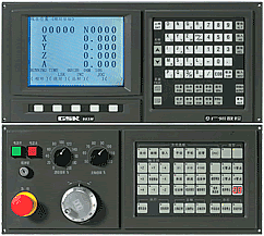
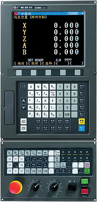
• 7.5inch 640 • 480 homochrome LCD screen ?machine coordinates, absolute coordinate, incremental coordinate, distance to move |
| • user program • current operation mode • system parameter, diagnosis number, alarm number, macro variable value, tool offset setting, MDI command, MST |
| State • actual federate, spindle speed • machining path graph |
| • Run time and other NC instructions and state information |
|
PMC function
|
Control method : cycle running; run speed:30us/step for basic instruction |
| Input/output : 192/128 ; 5000 steps |
| Development method: PMC instruction or ladder diagram |
| Instruction amount: 34 including 12 basic instructions and 22 function instructions |
| DNC function |
Serial DNC to connect U disc |
|
Support Manual
|
Controller 983M for milling/ drilling manual
|


