Controlled axes |
Controlled and linked axes: up to 4 feed axes, one spindle, 3 linked axes |
Interpolation method: positioning (G00), linear (G01), arc (G02, G03), helical interpolation |
Max. stroke: Metric: à¸à¸ 9999.9999 mm , least input increment: 0.0001 mm
Inch : à¸à¸ 999.9999 inch ฃฌ least input increment: 0.0001 inch |
Electronic gear: instruction multiplication coefficient 1 à¸à¸‹ 255, instruction division coefficient 1 à¸à¸‹ 255 |
Traverse speed: max. 30m /min
Rapid override: F0, 25 ฃฅ , 50 ฃฅ , 100 ฃฅ real-time adjustment |
Cutting feedrate: max. 15m /min (G94) or 500.00mm /r (G95)
Feedrate override: 0 à¸à¸‹ 150 ฃฅ divided into 16 level to real-time adjustment |
Manual feed override: 0 à¸à¸‹ 150 ฃฅ divided into 16 level to real-time adjustment |
MPG feed: 0.001, 0.01, 0.1mm |
Single step feedrate: 0.001, 0.01, 0.1mm |
Acceleration and deceleration |
The post acceleration and deceleration can be controlled in Manual mode, and the linear or exponential acceleration and deceleration, and the acceleration and deceleration time constant can be set.
MPG mode can select the instant stop and complete run, and the latter is for the acceleration and deceleration after interpolation, can select the linear or exponential acceleration and deceleration, and the acceleration/deceleration time constant can be set.
Positioning (G00) can select the linear or deflection positioning. The acceleration/deceleration before/after interpolation is optional. The acceleration/deceleration before interpolation is for the linear or S type, and the ones after interpolation is for linear or exponential. And the acceleration/ deceleration time constant can be set.
The system can pre-read most 15 blocks to foreknow the path and speed to get the high speed and smooth of small block, at the same time, it can select Hemert sample interpolation function, applied to the mold machining. The acceleration/deceleration before/after interpolation can be selected in the cutting. The acceleration/deceleration before interpolation can select the linear or S ones, the acceleration/deceleration after interpolation can select the linear or exponential ones, and the acceleration/deceleration time constant can be set. |
M instruction |
Miscellaneous function M: Specified by the sequential 2 digits after address M. |
Special M instructions(cannot be defined again):end of program M02, M30; program stop M00; optional stop M01; subprogram calling M98; end of subprogram M99. |
M codes are defined by the standard PLC: M03, M04, M05, M08, M09, M10,M11, M12, M13, M16, M17, M19, M21, M22, M32, M33 |
T instruction |
Tool function: à¸à¹‘T2 digistsà¸à¹‘256 group tool offset à¸à¹‘tool position offsetà¸à¹‘ tool length compensation à¸à¹‘tool nose radius compensation à¸à¹‘ communication input of tool offset valueà¸à¹‘ tool length measurement |
Spindle speed control |
Spindle function S: à¸à¹‘S 2 digits ฃจ I/O gear input and output ฃฉ / S 5 digits ฃจ analog output ฃฉ à¸à¹‘max spindle speed limit à¸à¹‘ constant surface speed |
Spindle encoder: resolutions can be set ฃจ 100 à¸à¸‹ 5000p/r ฃฉ |
Transmission ratio between encoder and spindle ฃจ 1 à¸à¸‹ 255 ฃฉฃบฃจ 1 à¸à¸‹ 255 ฃฉ |
Automatic compensation |
à¸à¹‘Storage bidirectional compensation of pitch error: compensation points can be set. It is used for compensating the error resulted by machine position(such as the pitch error of the feed screw ) to improve the machining precision. The compensated data as parameters are stored in storage. |
à¸à¹‘Backlash compensation: it can set the machine's momentum loss compensated by the fixed frequency or acceleration/deceleration. |
Tool length compensation: it is done by the specified G code (G43 ฃฌ G44 ฃฌ G49); the vertical plane can be selected by parameters. |
à¸à¹‘ Tool nose radius compensation (G40 ฃฌ G41 ฃฌ G42): C tool compensation
Max. compensation value: à¸à¸ 999.999mm or à¸à¸ 99.9999inch. |
Reliability and safety |
à¸à¹‘emergency stop ฃป à¸à¹‘overtravel ฃป à¸à¹‘stored stroke limit ฃป à¸à¹‘NC ready signal ฃป à¸à¹‘servo ready signal à¸à¹‘MST completion signal ฃป à¸à¹‘automatic run start light signal ฃป à¸à¹‘ automatic running signal ฃป à¸à¹‘feed hold light signal |
NC alarm: à¸à¹‘program or operation error ฃป à¸à¹‘overtravel error ฃป à¸à¹‘servo system error ฃป à¸à¹‘connection error, PLC error ฃป à¸à¹‘storage ฃจ ROM and RAM ฃฉ error ฃป over 300 alarms classified into 5 categories to provide the stable operation and rapid troubleshooting for the system . |
Historic alarm and operation record |
Self-diagnosis function to check the followings: à¸à¹‘ system abnormity ฃป à¸à¹‘ position control abnormity ฃป à¸à¹‘ servo system abnormity ฃป à¸à¹‘RS232 reading abnormity ฃป à¸à¹‘ PC data transmission abnormity and so on. |
Operation function |
à¸à¹‘ dry run à¸à¹‘ interlock à¸à¹‘ single block à¸à¹‘ optional block skip à¸à¹‘ Manual absolute ON/OFF à¸à¹‘ M.S.T. lock
à¸à¹‘ machine lock à¸à¹‘ feed hold à¸à¹‘ cycle start à¸à¹‘ emergency stop à¸à¹‘ external reset signal à¸à¹‘ external power ON/OFFà¸à¹‘ Manual continuous feed à¸à¹‘ incremental feed à¸à¹‘ MPG à¸à¹‘ skip à¸à¹‘additional optional block skip à¸à¹‘ sequence number search à¸à¹‘ program number search à¸à¹‘ external data input à¸à¹‘ program restart à¸à¹‘ menu switch à¸à¹‘ graphics displayà¸à¹‘ MPG interruption |
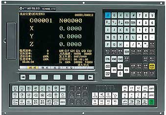
Display |
à¸à¹‘10.4 inch 640จw480 chromatic LCDà¸à¹‘ machine coordinates, absolute coordinates, relative coordinates, residual movement |
à¸à¹‘ User program à¸à¹‘ current operation mode à¸à¹‘ system parameter, diagnosis number, alarm number, macro variables, tool offset setting, MDI commands, MST |
State à¸à¹‘ actual feedrate, spindle speed à¸à¹‘ machining path display à¸à¹‘ real-time wave diagnosis |
à¸à¹‘System running time and other NC instructions and state messages |
Program edit |
Program capacity: 56M , max. 400 programs, customer macro calling and 4-level subprogram built-in are available |
Background edit, absolute, relative coordinate and complex coordinate programming are supported |
PLC function |
Control mode: cycle run; processing speed: 3ฆฬs/per basic instruction; max. 3000 steps |
IO unit input point/output piont: 48/48, expandable |
Development method: PLC instructions or ladder |
Instruction amount: 40 including 10 basic instructions, 30 functional instructions |
DNC function ALCE |
Serial DNC, and the baud rate can be set |
Communication |
Standard RS-232 and USB interface |
Bidirectional transmission of programs, parameters and ladder between CNC and PC |
Optional drive |
DA98 Series Digital AC Servo or DY3 Series Stepper Driver with input pulse and direction signal |
Support Manual |
Controller 218M for milling/ drilling manual A
Controller 218M for milling/ drilling manual B |